FIELD TIPS
décembre 12, 2017
Know your limits: Drill rod bending capabilities and deviated hole applications
Deviated holes and drill rod limits
A common wireline coring challenge is to successfully drill deviated holes, without cracking or permanent bending of the drill string. Most operators understand that any deviation should occur over multiple rod lengths and that any portion of the deviation must not induce a bend load exceeding the capacity of any passing drill rod. However, a simple drill rod deviation rating is not available because the capacity remaining in each rod is highly dependent on its position in the string, drilling loads applied and past deformation. Ultimately, the capacity of any drill rod is determined by two limitations of its steel material: the elastic bending limit of the midbody material, and the fatigue limit of the male end material.
Joint material properties
All steels suffer from fatigue failure (brittle cracking, rapidly followed by separation) when subjected to alternating loading for a sufficient period of time (fatigue limit), such as bending a paper clip back and forth until it snaps. Consider that as a drill rod passes through a deviation, it is subjected to an alternating bend load. That is to say, with each rotation the material is subjected to tension through the outside of the bend and compression through the inside. Further, the magnitude of the induced bending load increases with the drill rod size and midbody stiffness (increases with resistance to bending).
TIP: Deviations are not recommended for ‘P’ size applications. Only HRQ™ V-Wall™ or HXQ™ W-Wall™ is recommended for deviations in ‘H’ size applications.
Figure 1 - Fatigue Strength

A simple engineering rule of thumb is that the fatigue limit can be avoided if alternating loads are limited to less than 50 % of the yield strength. However, this rule should only be used for steel that is otherwise unloaded, or under a compressive preload. For example, while rods near the drill bit are always under compressive thrust, rods near the drill rig are eventually subjected to pullback tension as hole depth increases (more so in dry hole conditions), which can drop the fatigue strength to less than 25 % of yield strength (depending on the amount of pullback, refer to Figure 1 above).
Similarly, a further drop in fatigue strength occurs in the male end where additional tension is induced by the make-up torque required in each joint. This reduction is partially offset when heat treatment is applied to rod joints, boosting material strength. Boart Longyear’s RQ™ and XQ™ (launching soon) drill rod joints feature 175 % material strength (compared to midbody material) whereas competing rods typically offer 140 %.
TIP: Always follow make-up torque recommendations to ensure that joints passing through a deviation remain closed while preventing excessive tension induced into the male end, in order to withstand the alternating bend loads.
An additional offset is available by utilizing flexible V-Wall™ and W-Wall™ (launching soon) midbodies. The reduction in midbody stiffness, approximately equal to the percentage weight reduction, reduces the bend load applied to the rod joints.
Given the discussion above, a simple “deviation rule of thumb” against fatigue failures is to choose the strongest rod joint, and the most flexible midbody, in the smallest size possible, planning any deviation spread over as many rod joints as possible, and at a depth where the least amount of pullback will be required through the deviation in order to complete the hole.
However, even rod strings in straight holes without any planned deviations occasionally suffer male end fatigue failures as a result of bending midbodies through unexpected dynamic load response, as discussed below.
Midbody material properties
Figure 2 shows a typical load (stress) versus deformation (strain) curve for a typical drill rod midbody material. All steels will elastically return to an unloaded shape when loaded below the elastic limit (straight portion of the curve) but plastically deform or bend when loaded beyond. Once a rod string is permanently bent, the torque required to turn the string increases significantly due to side loading and friction against the hole and casing, causing heavy midbody wear and potentially heat check cracking of female ends (a thin outer skin is embrittled by frictional heating and quenching in the drilling fluid). Further, the associated bending loads can cause male end fatigue failures, similar to deviation bending loads.
Figure 2 - Midbody Material Properties
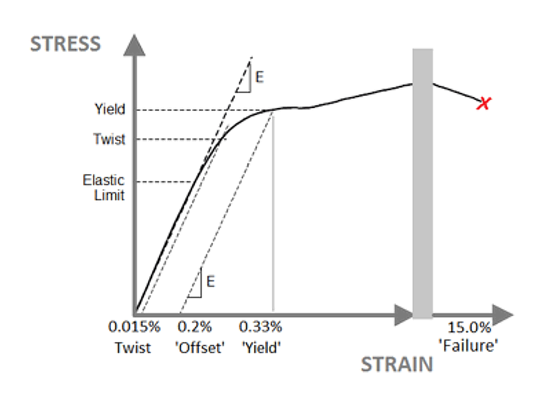
In the past, residual stress remained in the material which reduced the elastic limit, primarily caused by the final straightening step in the traditional cold-drawn tubing mill process. As a result, the typical elastic limit was well below the yield strength of the material as shown in Figure 2. Several years ago, Boart Longyear worked with North American tubing mill partners to develop a final thermal processing step, which eliminated residual stresses and maximized the elastic limit. Unique full-body bend test equipment was developed, capable of detecting a few microstrain of midbody deformation under alternating bend loads, which is now deployed for quality control and to ensure market leading performance. However, this material improvement does not fully address dynamic load response.
Dynamic load response and harmonic resonance
Over many years, permanently bent drill rod samples have occasionally been returned from the field for evaluation, i.e. tubing from different mills, of differing chemistries and processing etc. In addition to standard metallurgical examination results, full body bend testing has always confirmed that the drill rod material properties have not changed or degraded (unless the rod was subjected to cold-working by a roller-style rod handler, which reduces the elastic limit). In fact, some operators re-straighten rods using press straightening methods (for minimal cold working degradation) and are often fortunate enough to avoid a second bending incident, but not always.
Detailed 3D laser scanning of the deformed rod shapes shows that each drill rod is actually twisted into a partial helix that fits a helical (corkscrew) shape, typically forming a complete revolution (pitch) over four three-metre rod lengths, with a total run-out (amplitude) that fills the annular gap normally found between the rods and the hole or casing. This helical shape can typically be visually confirmed by a heavy one-sided wear pattern, the center point of which moves one-quarter turn on the circumference from one end to the other.
The deformation that is required to twist a rod into this shape is quite small, only about 0.015 % strain. As seen in Figure 2, this twist strain is an amount of strain that is significantly less than the 0.2 % strain used to determine the traditional yield strength. That is to say, permanently bent drill rods have simply yielded slightly, due to overload just beyond the elastic limit. Once bent and twisted into this shape, loading is transmitted into the hole or casing which leads to excessive torque and feed, preventing productive drilling, or a stuck string and potentially rod joint failure.
Once bent and twisted into this shape, loading is transmitted into the hole or casing which leads to excessive torque and feed, preventing productive drilling, or a stuck string and potentially rod joint failure.
Using Boart Longyear drilling expertise, this loading scenario was confirmed by recreating twisting incidents in separate Boart Longyear operations yards, with different rigs, in order to evaluate various “N” size test strings. Drilling with short test strings from the surface at a 45-degree decline into dry ground conditions, without flushing, ensures maximum drag with the rods in compression. Test strings have included new and used RQ rods (good condition), Q™ rods, and competing drill rods, including those claiming heat treatments for greater midbody strength. Prototype rods with midbody heat treatments were also tested, up to 140 % strength (similar to rod joints), which produced record-breaking results on the full-body bend test equipment. However, regardless of midbody material or heat-treated strength, any rod string can be easily driven into an uncontrolled dynamic load response. This generates drag and resistance to a point of overload (partly from the rig and partly from the inertia of the rod string) and deformation into a corkscrew shape which fills the hole and allows a sudden build of loads until the rig stalls or a rod joint fails.
TIP: When drilling vibration is evident, smartphone video recordings often allow for visual confirmation of a dynamic load response and helical whirling, not otherwise discernible to the naked eye.
Fortunately, the energy drilling industry (oil and gas) has also suffered from string buckling, heat check cracking, fatigue failures, and midbody bending as a result of dynamic load response. Boart Longyear has employed the expertise of several oil and gas engineering consultants in recent years, to develop a full understanding of these phenomena including the following “dynamic” elements.
First, consider that all rod strings quickly become unstable.
First, consider that all rod strings quickly become unstable. Rod strings will elastically buckle under their own weight, and will actually “helically buckle” (corkscrew shape) under significantly less weight given torque and rotation (helical whirling). However, there is normally enough stiffness in the buckled shape to allow drilling without excessive drag against the hole, and rod strings elastically return to straight once rotation is halted, without any deformation.
Depending on the weight on bit, approximately the first 100 rods are always in compression and subject to buckling, whereas rods above are dampened with pullback tension. The maximum bending and twisting load stresses possible are limited by the annular gap between the rods and the hole or casing. Casing to significant depths with rods introduces a larger annulus, allowing a tighter corkscrew deformation with significantly greater stresses. Further, some operators have used V-Wall rods as casings, providing significant lengths with even larger annulus, and then reported an increased frequency of twisting incidents. Similarly, the new PHD W-Wall, NXQ and HXQ W-Wall rods (launching soon) feature a mid-placed section of standard wall thickness which provides support to nested rod strings (when used as casings) while still providing an equivalent weight reduction.
Second, once buckled into an elastic corkscrew, the rod string acts like a long coil spring wherein any sudden changes in drilling loads or hole drag are dynamically magnified and reflected in waves, up and down the rod string. These load and drag changes can occur anywhere in the rod string, typically caused by sudden changes in ground conditions or in hole deviation. For example, directional drilling applications induce reaction loads against the hole, which provides points of high contact pressure where “stick-slip” conditions can occur that then initiates a dynamic load response.
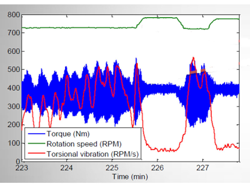
Third, as with any elongated vibrating or rotating system, rod strings are subject to natural resonant frequencies or harmonic resonance where under critical rotation speeds, small input loads (excitation) produce very large output loads and deformations (resonance). The chart in Figure 3 demonstrates how the critical speeds for any rod string can be avoided with small speed adjustments at lower depths, but this becomes more difficult with increasing depth. For example, the field experiment data acquisition results, charted in Figure 4, show how torsional vibration was dramatically reduced with only a small adjustment in speed.
Figure 3 - Avoiding Critical Speeds
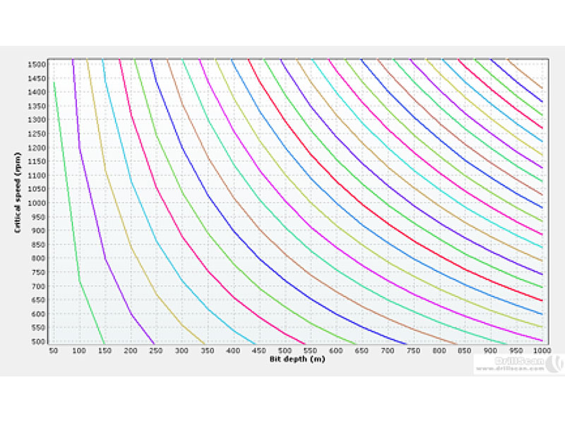
Figure 4 - Avoiding Dynamic Load Response
In conclusion, all rod strings are inherently limited in bending capability and are sensitive to hole deviations. Deviations should be minimized and well planned to avoid dynamic load response and potential overload. Vibration should be minimized by adjusting rotation speed to avoid the load amplification of natural frequencies. For demanding applications, always select a drill rod with the most capable midbody material, and a threaded connection with both wear resistant case-hardening, and high-strength thru-hardening to better withstand both drilling loads and dynamic load response.
CORING RODS AND CASING CATALOG
Download a PDF of the Coring Rods and Casing Catalog
DOWNLOAD
[pardot-form height="770" id="1793" title="Download Coring Rods and Casing Catalog"]