EXPLORATION
October 22, 2018
Understanding and Preventing Heat Check Cracking on Drill Rods
What is Heat Check Cracking?
Heat check cracking is the engineering term describing the brittle cracking failure of steel, wherein a thin surface layer has become excessively hard and brittle as the result of rapid cycles of frictional heating and cooling.
The frictional heating is the result of ‘rubbing’ contact or ‘drag’ against a mating surface. Friction heat can build to exceed the transformation temperature of the steel (or ‘austenite transformation start temperature’, ~750degC/1350degF), followed by rapid cooling from surrounding steel or cooling fluid, hardening, and embrittlement. When this cycle repeats frequently, the heating and cooling create rapid expansion and contraction which leads to fatigue failure, seen as perpendicular cracks that propagate from the surface.
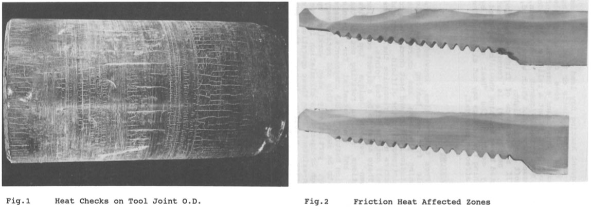
Figure 1 – Oil & Gas Tool Joint with heat check hardening and cracking
While this phenomenon is well documented in engineering texts, the problem has been prominent in the oil and gas exploration industry since the 1940’s. The API (American Petroleum Institute) describes heat check cracking as, “Formation of surface cracks formed by the rapid heating and cooling of the component” (API ‘RP 7G-2, Recommended Practice for Inspection and Classification of Used Drill Stem Elements’, and ‘RP 96, Deepwater Well Design and Construction’.)
A 1992 IADC/SPE paper on heat check cracking described full-scale simulations to prove that the heating and hardening are easily achieved, but that fatigue cracking only results from the rapid heating and cooling associated with each rotation of the drill string.
How does Heat Check Cracking develop on Wireline Coring Rods?
As shown in these pictures of wireline coring drill rods, heat check cracking can actually be easily identified, visually in the field. Heat check cracks are unique in that they follow the axis of the rod (longitudinal or ‘axial’ orientation), and are located near the female or box end shoulder, and are associated with a shiny, polished wear area. This section of the box always protrudes slightly more than any other area on a wireline drill rod and grows or ‘bulges’ under high drilling loads.
‘Box bulging’ is the result of a) the interference fit between the pin and the box (which is responsible for keeping the joint closed under deceleration ) and, b) the compression of the box shoulder under torsion and any radial loading from the thread-form. The positive load flank angles of traditional thread-forms, such as Q™ threads, generate radial load components that can increase box bulging to the point of separation, whereas premium thread forms with reverse-angle load-flanks, such as RQ™ and XQ™, actually limit box bulging.
Since heat check cracks are the result of fatigue loading, they always start from the surface and form perpendicular to the direction of the expansion and contraction which is longitudinal or axial on a drill rod and easily pass across turns of thread. Fatigue failures that result from excessive drilling loads or excessive deviation always produce cracks that start internally and form perpendicular to the axis, or circumferentially, and typically follow the thread. In other words, since there are no drilling loads that act circumferentially, the only way to form longitudinal or axial cracks is through rapid heating and cooling.
Also, consider that the fatigue strength of any steel is less than only 50% of its normal ‘yield strength’ and that hardened steel is much more brittle than tempered steel. When subjected to excessive fatigue loading, the maximum expected life of any steel is less than three million cycles of alternating load. In terms of a spinning wireline drill rod, this represents less than a few days operation—at most. This same material limitation is behind fatigue failures in drill rod joints when subjected to excessive deviation (refer to our earlier article, “Drill Rod Bending Capabilities and deviated hole applications).
These limitations hold true for all wireline drilling industry carbon and alloy steel grades, all tube forming processes, all parallel and variable wall tubing, and all heat treatment configurations. This is because the transformation temperature is determined by carbon content, and does not worsen significantly without abnormally high levels of carbon (for example, the grade AISI/SAE 1541 has excessive carbon and a reduced transformation temperature, which was a common grade before heat treatment became popular). Also, whether a drill rod was initially heat treated or not, steel will transform when frictionally heated above its critical temperature, regardless of previous material properties.
Figure 2 – Various wireline coring drill rod samples with heat check hardening and cracking
Further, these material limitations hold true regardless of whether a drill rod is new or used, i.e. transformation properties do not change with use. Operators who suffer from heat check cracking often claim to have older rods that did not crack, which is just a coincidence. That is to say, whether or not a heat check cracking incident occurs depends on a difference in the loading – possibly in the same hole – rather than any difference in the drill rods.
Avoiding Heat Check Cracking Failures
In summary, ‘heat check cracking’ is the result of an application issue where there is heat generated by a) lateral contact pressure and, b) insufficient lubrication, leading to fatigue failure.
Lateral contact pressure, or ‘drag’, can obviously be created with a misaligned drill rig or when the drill rod string passes through a deviation, but more typically is associated with drill string buckling, due to excessive drilling torque, rotational speed, and thrust or ‘weight on bit’. A reduction in any of these operating parameters will reduce the lateral contact pressure. However, in some cases drill rod midbodies may have been permanently twisted or ‘bent’, due to dynamic overload or due to roller rod handlers, which adds to lateral contact pressure. Always minimize fatigue and lateral loading by limiting hole deviation “dog-legs” (total deviation in dip and azimuth) to less than 1 degree per rod length, monitoring with tight hole survey intervals, and corrective reaming operations (limit to less than 0.6deg per rod in larger diameter holes). Avoid dynamic loading and rod twisting by maximizing spacing between multiple deviations and by eliminating neighboring deviations with opposing or divergent directions. Alternatively, select a free-cutting drill bit which will allow for reduction in torque and thrust. Use a Boart Longyear™ shoulder thickness wear gauge to inspect for un-even wear around the box shoulder circumference, which can provide an early warning to adjust operating parameters or improving lubrication.
It is helpful to apply and maintain an appropriate lubricant or grease coating on the outer surface of the drill string which can directly reduce the friction factor and the heat generated. During rod pulls, visually inspect how the coating has worn away as a good indicator of the degree of lateral contact. ‘Shiny one-sided’ wear patterns, either at the box ends or with a ‘slow’ one-quarter spiral turn over the rod length, indicate excessive loading.
While drilling fluids contribute to heat check hardening by quenching heated surfaces, maintain a high fluid pressure and consider polymer additives to improve lubrication, and reduce frictional heating and quench severity.
Finally, consider this recommendation from the IADC/SPE, “When users are confronted with the cause of failure, the initial reaction is often disbelief…It is difficult to believe that tool joints can be heated above their critical temperature while drilling…in the presence of mud circulation. From time to time, knowledge of the in-hole friction heating and cyclic quenching phenomena and characteristic longitudinal cracks need to be reintroduced to the field. Users and inspectors need to recognize the evidence and cull out the affected joints.”
DOWNLOAD PDF
Download the full PDF of Drill rod threads: tips to avoid common problems and improve productivity
DOWNLOAD
[pardot-form height="770" id="2405" title="Download Drill Rod Threads PDF"]